Contents
Thevenin’s Theorem
Thevenin’s theorem is the theorem that is applicable where we have to find the voltage or current across any one element in a network without going through the rigorous method of solving a set of network equations.
we usually see in practice that a particular element present in a circuit is variable and is usually called the load while the other elements present in that circuit are fixed.
Let us consider an example of a household outlet terminal that may be connected to different types of appliances, constituting a variable load. Here each time the variable element is changed so the whole circuit has to be analyzed all over again.
To avoid the above-discussed problem, Thevenin’s theorem provides a method by which the fixed part of the circuit is replaced by an equivalent circuit.
Thevenin’s theorem was developed by a French telegraph engineer named M. Leon Thevenin in 1833.
Thevenin’s theorem statement
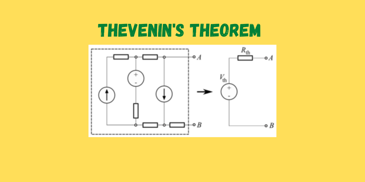
According to Thevenin’s theorem, “A linear bilateral network containing one or more independent or dependent voltage or current sources can be replaced by a single voltage source and a series resistor connected to the load”.
The general statement of this theorem is that any linear active network consists of independent and or dependent voltage and current sources and linear bilateral network elements can be replaced by an equivalent circuit consists of a voltage source and a resistance in series.
The voltage source is the open-circuited voltage across the open-circuited load terminal, and the resistance is the internal resistance of the source network looking through the open-circuited load terminal.
Steps to solve a network using Thevenin’s theorem
- First of all, remove the load resistance present in the circuit.
- Then find the open-circuit voltage across the open-circuited load terminal(i.e, VOC or Vth).
- Find the equivalent Thevenin’s resistance across the open-circuited terminal(i.e, Rth).
- Then obtain Thevenin’s equivalent circuit by connecting a source voltage Vth in series with a series resistance Rth.
- Finally, reconnect the load resistance(RL ) across the load terminal.
Obviously, the load current,
I = V OC/Rth+RL.
Different methods to find Thevenin’s equivalent resistance(Rth).
For independent sources: It is the most common method of finding Thevenin’s equivalent resistance. In this method, the voltage source present is to be short-circuited and the current source present is to be open-circuited.
Then Thevenin’s equivalent resistance Rth for the network is to be calculated by looking through the load terminal kept open-circuited.
For the circuit containing dependent sources in addition to or in the absence of an independent source:
1stmethod-First of all, the voltage across the open-circuited load terminal (VOC)is calculated by the conventional network analysis. Then, short-circuit the load terminal and find the short-circuit current(ISC)through the short-circuited terminal.
i.e Rth=VOC/ISC
2nd method-In this method, first of all, remove the load resistance and apply a DC driving voltage Vdc at the open-circuited load terminal. And all the independent sources are kept deactivated during this time, i.e, voltage source terminals are shorted and current source terminals are open-circuited.
Then a DC driving due to the application Vdc. Then the value of Thevenin’s equivalent resistance is given by
Rth =Vdc/Idc
Thevenin’s theorem example

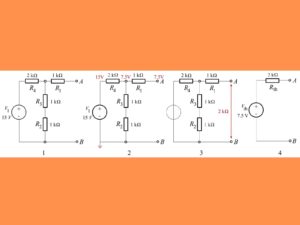
In the above figure, a circuit is given whose Vth, Rth, and Thevenin’s equivalent circuit are to be obtained.
Fig. 1 shows the original circuit.
The first step is to find the value of Vth
Vth =(R2+R3).V1/ (R2+R3)+R4
Vth=(1kΩ+1kΩ)×15/(1kΩ+1kΩ)+2kΩ
Vth= 1/2 ×15=7.5
Here it is important to note that R1 is not considered in the above calculation, as it is done in an open circuit condition between A and B so no current will flow through this R1 resistor and therefore will be no voltage drop along this part.
Calculate equivalent Thevenin resistance
Rth =R1+[(R2+R3)||R4]
=1KΩ+[(1KΩ+1KΩ)||2KΩ]
=1KΩ+( 1 /1KΩ+1K Ω + 1/2KΩ )-1=2KΩ
In this way, we can calculate the value of Rth and Vth for a given circuit.

Jitu Kumar is the Founder and Senior Content Head of Electrical Maker. On electricalmaker.com, we publish the latest educational updates regarding Engineering.
